Experimental Off-Carriage Extruder Motor
There was a recent thing on Thingiverse called the Vert-X-Belt-Truder by Johann which describes a way of moving the extruder motor off the carriage. The benefits are a lighter, and potentially faster, carriage. The Bowden cable is another way of achieving this goal. A comment by Martin Price (martinprice2004) caught my eye:
...keep the x axis as current prusa, but turn the extruder 90 degree around the z axis. Drive the extruder using a motor mounted at the end of the axis with a square or hexagon bar mounted horizontally. The extruder drive gear moves along the shaft when the x axis moves, but can still be driven by the motor at any point.
I had already done something similar for moving the X-axis motor off the carriage and so I quickly threw together a proof of concept to thrash out how a design would work.

Sketchup Design
The results are shown in the following video (please excuse the varying focus, the many "er"s, and the fact the audio is muffled between 2:10 and 3:35 - I didn't realise I had my finger on the microphone - but I don't say much of value here anyhow, only that it seems to work and the drive gear moves through the drive shaft. Also that the test "print" is running at 200mm/s (travel:250mm/s))
I utilised the Compact Geared Extruder by Matt Roberts (Thingiverse) because it's small, modular, and as it is designed in OpenScad it's easy to hack with. I went through a couple of iterations to come up with a bracket that would hold the drive gear in place as the extruder moved along the square drive shaft. As I put the parts together I realised the same effect could be achieved using herringbone gears, so long as the drive gear is held close to the driven. The coupling is a rubber roller from an old Xerox laser printer, as is the square rod. The NEMA 11 motor is simply zip-tied to the X-axis motor end, and the idler is simply a bearing zip-tied to the X-axis Idler end.

A few things I learned as I put it together which might be worth considering if anyone recreates this.
- Positioning of the motor and idler dictate where the drive gear will be placed, and so I would align these precisely with the X-axis rods and place the drive gear with a bracket. Then I would make position of the extruder flexible (using slots for the bolts for example) so it can be accurately pushed back in line with the drive gear, giving a good fit.
- The bracket holding the drive gear would be made more robust - reducing lateral movement and possibly adding bearings or bushings either side of the drive gear to support the rod.
- The bracket should have a way of removing and inserting the square rod, otherwise it'll be a pain to disassemble the whole thing. Of course if bearing or bushings are used then it might be easier to design it so the rod slides out along the X-axis when disassembling.
- As mentioned above, using a helical gear such as a herringbone might remove the need for a bracket at all. I guess this would depend on the amount of flex along the driveshaft, and whether the drive gear keeps engaged during the back and forth.
If I get chance to fix the hobbed bolt of the compact extruder then I will try to get this setup printing for real. Here's a couple more photos and videos just of the running.
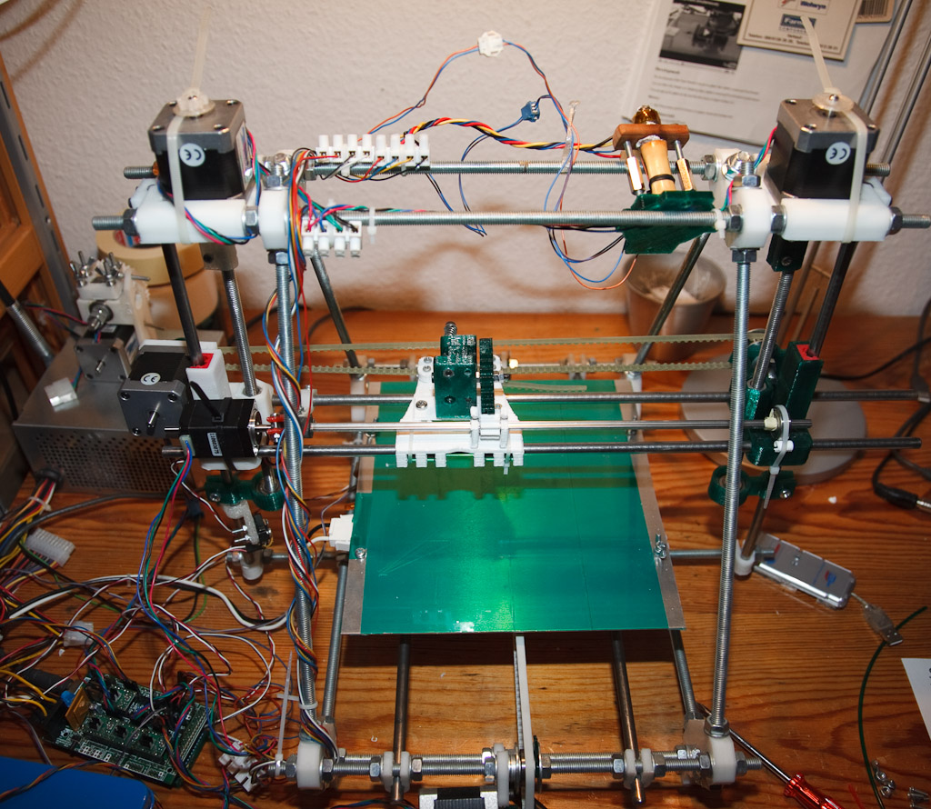
Overview
Drive Gear Bracket 2
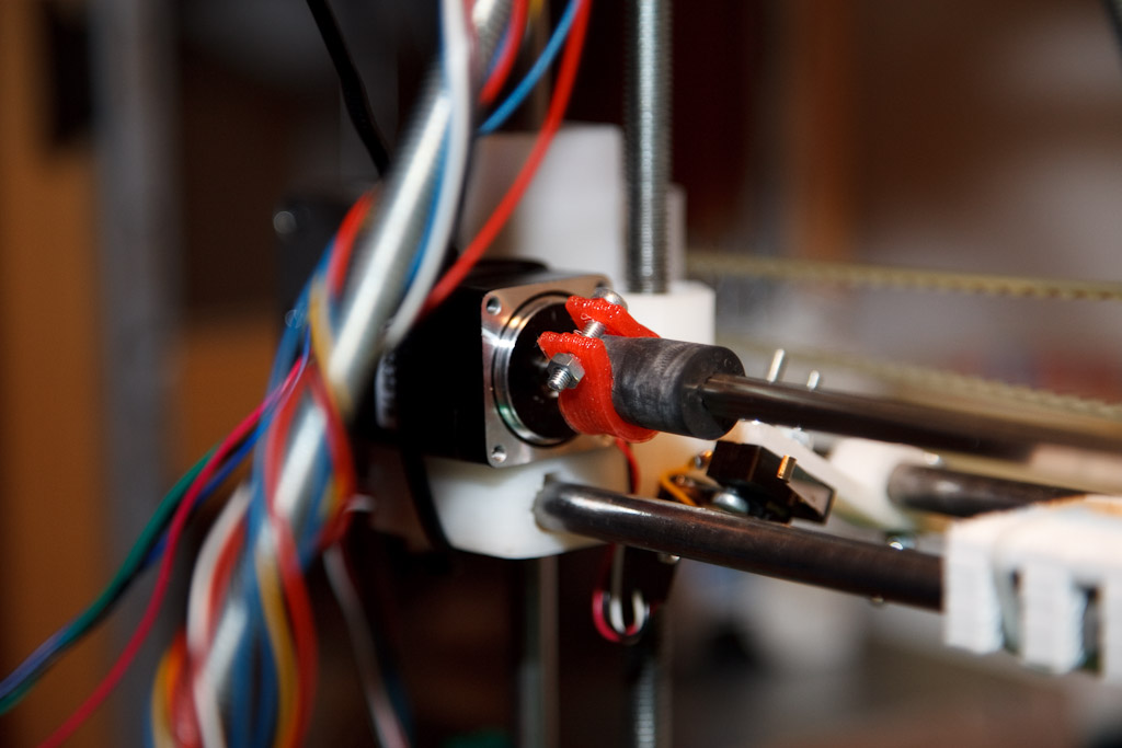
Motor
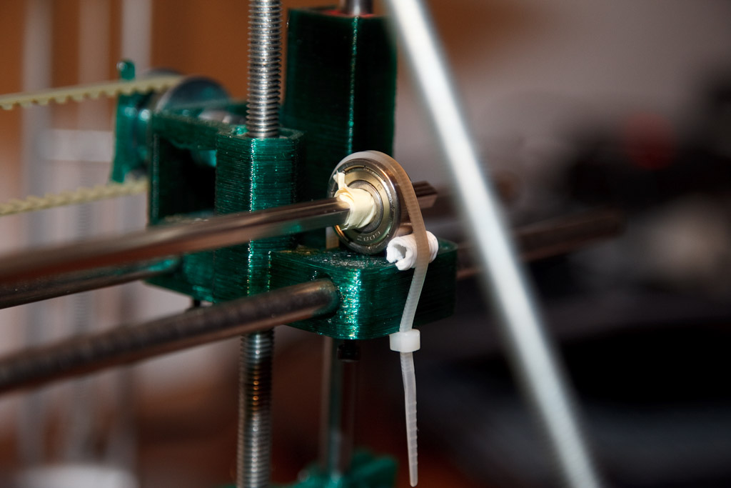
Idler
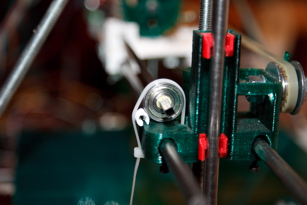
Idler-2
Comments
-
Billy Zelsnack
08-01-2012 04:10
Very cool. I've been wanting to experiment with this floating gear concept, but seeing it in action makes me want to try it more! I think this setup really could come into its own when extended to two extruders. I look forward to it see how well it works out during actual extruding when the friction is at its greatest. I guess if that's a problem you can just keep upping the motor size until it is not.
-
Brad Pitcher
08-01-2012 07:16
That is so awesome! I definitely want to do that on my RepRap at some point. As it is, I'm already nearly done with some other upgrades that I've been working on for a couple weeks now. Maybe I'll shoot for the next maintenance cycle. Good work!
-
Sanjay Mortimer
08-01-2012 11:52
Really enjoy this concept and your test rig is awesome, you do some good work on it.
I agree it would very interesting to see how a herringbone gear would cope with the lateral forces. I think perhaps herringbone gear with flanges would be a safe bet.
If you had the large driven gear with two flanges that would help keep the small driving gear in place, but printing a gear with two flanges would be tricky because of the overhang.
You could instead have one flange on the driven gear, and one flange on the driver gear. With the flanges on opposite sides to each other. This way you would be constrained in both directions with both flanges and herringbone with all printed parts.
How is the friction on the driving gear as it slides along that square rod? I had a cursory look for square bushings and came up with this: http://www.alibaba.com/product-gs/234284591/Plastic_Square_Bushing.html
Keep up the awesome work!
-
whosawhatsis?
08-01-2012 18:41
Cool idea, though it would be nice to move the gearing off the carriage too so that you have even less weight and so that the square shaft moves slow (might cause less wear). You would need a drive gear machined to fit the square shaft, but out drive gears need to be machined anyway, and metal (or PTFE, or other machined material) bushing interfacing the gear to the square rod. If the drive gear uses a groove hobbed with a tap as we do with bolts, the drive gear should keep itself centered on the filament.
-
Gary Hodgson
08-01-2012 20:18
That's an interesting idea. I just had a dig around my junk box and found some interesting one-way bushings that could be used together (either direction) to hold a hobbed insert in place around a round rod, but leave it free to move along it. Or, using a hobbed insert with a round hole with four corners drilled out might work, but would have to be pretty precise. If I get a chance I'll put together a proof of concept, or at least draw what I mean :)
Also, one could probably go to the extreme and remove all motors from the entire X-axis - using a bevel or worm gear to change the operating angle by 90° to drive the extruder, and perhaps using something like the off-carriage x-axis design I played with. Perhaps such a design would be useful for your printrbot variant to remove all weight from the Z rods?
-
Gary Hodgson
08-01-2012 20:26
Hi Sanjay - Alternating flanges is a good idea for holding the gears in place without a bracket!
The drive gear is printed out of PLA and has reasonably little friction so it slides quite well. If I was to make another iteration I would provide more support for the rod and the bracket - possibly with bearings. Using brass square-bushings would extend the life of the gear I guess.
-
whosawhatsis?
08-01-2012 22:15
Actually, my design needs MORE weight on the Z rods. The x axis rests on top of the nuts as a safety feature (like the Cupcake's Z platform, so the axis will lift in case of a head collision), but it's so light that the idler end has a habit of sticking on the rod and lagging behind the other end when it's going down. Putting the extruder motor on the idler end would balance it out and solve this problem.
-
dmeehl
11-01-2012 03:27
Great job. This is an idea I also had but ultimately I went a different route because I was worried about friction along the square shaft while both motors are in motion. Instead I used a differentially driven belt. So far my idea is just a design though I'd like to test it as soon as possible. You can see my design here http://www.thingiverse.com/thing:15445
-
elk
14-01-2012 11:39
did you use it also under load? I guess as soon as it runs under load, there will be remarkably more friction on the little drive-gear. Perhaps a rectangular bushing made of brass (or bronze) will do the job...
all in all i think it is an interesting idea but i guess it makes the build quite a bit more comples (and a rectangular rod will be necessary as "vitamin" part). Despite this, keep up your good work!
-
Sanjay Mortimer
15-01-2012 18:03
This could well be a useful part/inspiration for a part:
http://www.thingiverse.com/thing:15995
-
Gary Hodgson
15-01-2012 19:28
Nice find!
-
EmmanuelG
16-01-2012 22:10
Waw ! I didn't believed it will work, even more impressed =)
-
Enrico Cianni
30-01-2012 00:04
If you move the idler at the end of the square bar so that it is on the extruder carriage, just to the right of the driver gear so that it is attached to the carriage, and allow the square bar to slide through the bearing, you would not have to worry about the driver gear pulling away because of the rod bowing. You would need a square-to-round insert with low friction on the square side (maybe 4 "U" shaped brass inserts covering the inner square edges) that fits nicely into the round bearings' inside. The end of the square would then just need a very loose round hole, just to stop it from rattling around.
-
Gary Hodgson
30-01-2012 08:54
Hi Enrico, you're quite correct! I recently spent a few minutes hooking this up to a hot-end and attempting to extrude, and indeed the square rod bowed too much when under pressure. This is purely because my implementation is poorly cobbled together - a more solid housing for the driven gear, as you suggest, would solve the problem. Interestingly, my initial go at this involved a square-to-round insert for a 608 bearing - but I had attempted to make the insert and drive gear in one piece, and my print didn't fit well enough. If I find time I will give your suggestion a go.
-
Enrico Cianni
31-01-2012 01:50
Hi Gary,
I'm glad my Idea had merit - and I like yours even better! I was initially going to suggest a bearing on each side of the drive gear to hold it rock-steady, but thought that might be over-kill. Even worse, with 3 thin separate points of contact, each of which could potentially tilt off-plane as they are shuttled back and forth, you could end up with binding issues.
With the drive gear affixed to the square-to-round insert, the gear is stronger due to the extra material. Also, the contact area of the square rod through the square hole is longer, which will make the whole thing more stable in the plane normal to the rod. Depending on the space requirements, you might even extend the square-to-round insert to the left of the gear, as if you were going to put another bearing on that side, but just for stability.
-
Enrico Cianni
02-02-2012 01:36
I haven't built a printer yet, just doing research. If I had thought about my last post, I would have realized you couldn't print the extension to the left, as it would require an over-hang. Quite the noobish mistake!
-
Brain S
28-02-2012 15:51
Good show!
I know you have this nailed. I've been sketching and mocking up for several months. Just too short sighted to the square from the round. :-)
-
Martin Price
29-04-2012 02:30
Gary. The design looks like it has a future. As suggested above, shaft driving the large extruder gear is the next logical step, but how about a step further. Drive the hobbed bolt directly. A larger diameter hobbed bolt with a square hole. Then a bearing either side with the square shaft passing right through. All gearing at the end of the X carriage. The extruder would be tiny.
Square holes are hard to find, but brass keys for venting domestic radiators have them. An alternative would be to use a heaxgon drive bar and use a modified hexagon socket with the outsided roughed up with a dremel to grip the filament. (cheap socket sets found for £2 at petrol stations!). Another source would be the to use the head of a socket cap screw.
-
Johan Schreiner
16-04-2013 22:15
Hi Gary,
I saw you off carriage extruder solution when you first released it, and I found it really interesting. I have two printers with Bowden-setup, and I am having issues with finding the right retraction settings at high speed.
I were discussing your solution with RoTorIt at the norwegian IRC, and he sugested to replace one smooth rod with the new rotating extruder-shaft. I went further, and started designing a new dual extruder x-carriage using two hex rods as both linear shafts and extruder shafts.
I am printing the last parts now, and will assemble the new printer in a couple of weeks.
I aware of the posibility of the whole system beeing wobbly, but the prints look good, with a nice tight pressfit. I am more optimistic now than when I started printing the parts! :-)
Her are some screenshots of the new printer:
https://dl.dropboxusercontent.com/u/55953222/Duohex%201.JPG
https://dl.dropboxusercontent.com/u/55953222/Duohex%20X-carriage.JPG
Johan
-
Gary Hodgson
17-04-2013 08:42
Hi Johan,
That looks great and I can't wait to see it built and in action! Do you have a blog or something I can follow the progress on?
I always wanted to develop the idea beyond the proof of concept phase, but getting it higher in my to-do list has proven difficult, so it will be great to see a real implementation.
One idea I have been playing around with since then which might be of interest is a way to use one motor for two extruders. It uses 2 one-way ring bearings, running in opposite directions to each other. (I can sketch the design if you like.) Each bearing would be within a gear driving an extruder. The main problem of course is that there would be no way to retract the filament using the motor. I thought perhaps a spring pushing back on the filament might be used as an alternative, but haven't mocked up anything beyond the ring bearings. Maybe it's just another silly idea, but if it could be made to work then it would allow for 4 extruders on your machine :)
Anyhow, I hope you will keep me up to date with your progress!
Best of luck,
Gary
-
Johan schreiner
29-04-2013 16:23
Hi,
Sorry for late reply...
I have no blog. I have posted some screenshots on the norwegian reprap forum, but nothing much.
I had to redesign and reprint the x-ends, and part of the frame.
The way the hex rods are fixed in the bearings in the x ends isn't as rigid as the smooth rods in normal x ends. I had to go from one to two z smoothrods to avoid the x-ends rotating....
Johan